-40%
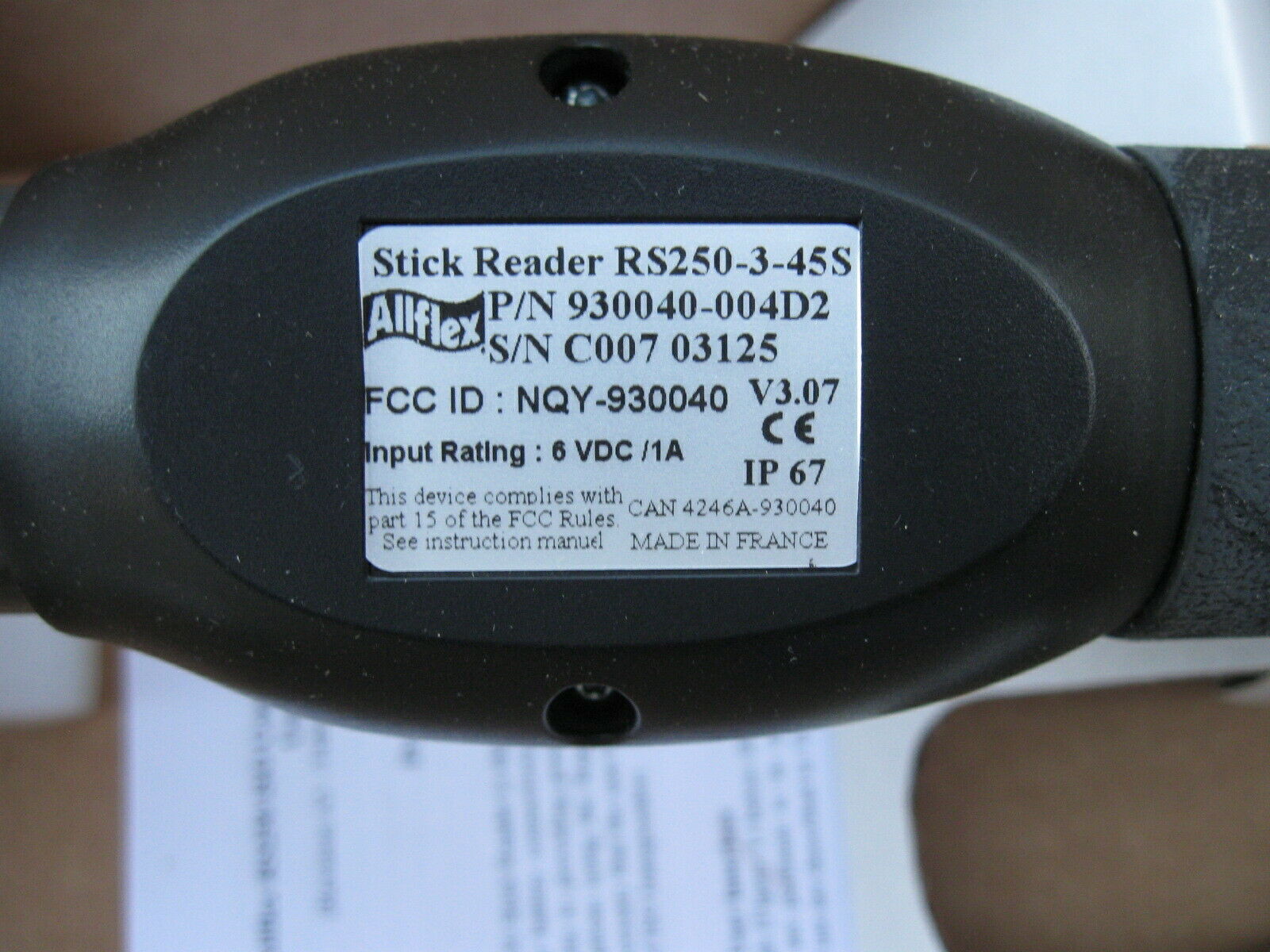
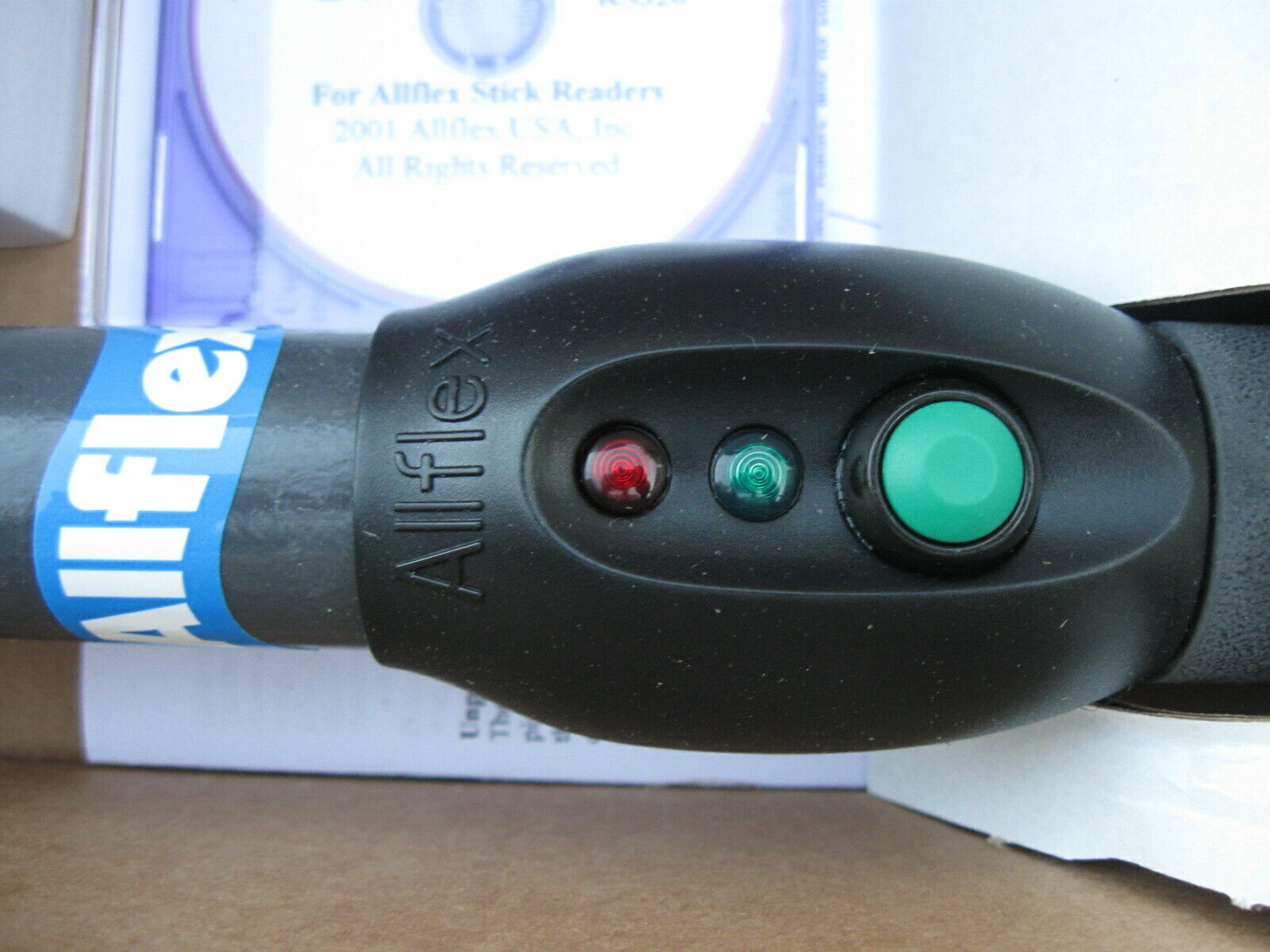
ALLFLEX RS250-3-45s, 930040 Animal Livestock ID RFID Chip Tag Stick Reader New
$ 36.96
- Description
- Size Guide
Description
Up for sale is anALLFLEX RS250-3-45s, Part# 930040 Animal Livestock ID RFID Chip Tag Stick Reader
. New surplus equipment in the open box.
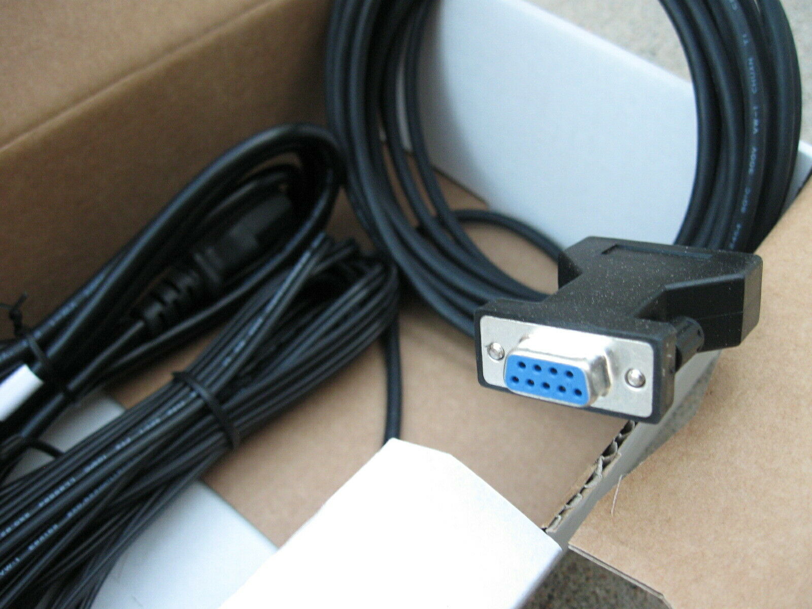
Please view the photos for what you get. I have many of these if you need more than one.
This model does
not
have a battery contained within the stick. See below in the description of different ways it can be powered. One way is by the power adapter and cable included in the box. User manual and Software CD included. Allflex Stick Reader Configurator v2.19 for
Windows 95, 98, 2000, and XP
. Works with RS250 and RS320.
It will be shipped in it's original box, and not boxed inside of another one.
**The user manual can also be found on the internet by Google searching for "Allflex 930040 user manual". **
***If you want to download the Allflex EID Tag Manager User Manual online, google that and you can find that too. I can't post the complete site on ebay because it will be deleted, but put "WWW" in front of this below to get the EID Tag Manager User Manual...
atq.qc.ca/images/stories/fantome/Allflex/eid%20tag%20manager%20user%20manual_ver1_ang.pdf
Just some information found in the manual....
Power Source Requirements:...
The Stick Rea
der can be powere
d from
a variety of DC po
wer source opt
ions, either
through the DC powe
r jack or throu
gh pin 9 on the DB9F con
nector. Recomme
nded
DC Power sources are the Allflex PW50, PW
250, or RFL100
Portable Recharg
eable
Battery Pack, or PW409
AC Power Supply,
which attaches to the DC Power Jack.
Note 1
-
Certain weigh scales and other equipm
ent to which the Stick Read
er can be attached
provide DC power on pin 9 of the DB9 interf
ace connector.
Such DC power sources are
acceptable as lo
ng as the voltage is betwe
en
6 and 12 volts DC, and are capable of providing
at least 500 milliamperes continuous
current, and at least 1.0 ampe
re peak current. Pin 5 of
the DB9 connector is ground. A rechargeable seal
ed lead acid battery rated at 6 volts and 4.5
ampere-hours or greater is an excellent
choice for portable and
field appl
ications.
Note 2
-
When an extern
al power source is co
nnected to the DC Power Jack,
inserting the
plug causes electrical continuity to pin 9 of th
e DB9 connector to be interrupted. Polarity on
the DC Power Jack is sleeve + and cente
r pin -. The DC power plug specification
is a 2.5mm
x 5.5mm DC Coaxial (9.5mm length).
Note 3
-
An AC power supply must be a linear
regulated type unit rated at 6 to 12 VDC
output and 1.0 amperes mi
nimum. Some AC power supplies
may exhibit excessive noise that
can compromise read range of FDX-B type transponders. Suitable AC power supplies should
be rated at 3 millivolts or less output ripp
le.
Note 4
-
The Stick R
eader does not contain a p
ower on/off switch. When a power source is
connected to either the power jack of pin 9
of the DB9F connector, the Sti
ck Reader will
consume an idle current of appr
oximately 25 milliam
peres. When powered fr
om a battery
source, be sure to disconnect the battery when
the Stick Reader is not in use in order to
conserve battery life.
Note 5
- The Stick R
eader is polarity prot
ected
against accidental reve
rse voltage application
and will not be damaged by such.
ID Code Memory
The Stick Reader contains an intern
al non-volatile memory capable of storing
1638
ID codes. ID codes are st
ored autom
atically
upon being read. A tra
nsponder ID
code will not be stored multiple times if
read multiple times successively, but can be
stored in memory multiple ti
mes if other tags
are read in between.
All ID codes are
retained when power to the Stick Reader is
shut off. If more tha
n 1638 ID codes are
read, the new ID codes are written over
the old
est ID codes in a wrap-around
manner.
ID Codes can
be retrieved
from the St
ick Reader via it
s RS232 serial
port by i
ssuing
to the Reader a
ble 5
on page 9
). The
and can be
issued as many times as desired
, and the complete memory conten
ts will be
transferred upon each event. ID codes a
r
e not erased from
the memory until a
command is
received.
Each ID code is followed by a
e return/line feed) which will
cause each ID code to appea
r on a separate
line of a PC di
splay. The Stick Reader
contains a configuration
option that automatically in
serts a null identification code in
memory upon applicatio
n of power to th
e Reader. This provides a means of
establishing partitions in
memory between bl
ocks of ID codes that represent separate
groups of identified animals, thus facilitati
ng
the management o
f ID code data once
downloaded to a PC d
atabase. To set this partitio
ning marker, use the command
fault state is
M00).
Stick Reader Physical Integrity
The Stick Reader has been con
structed from
rugged and durable materials to provide long
periods of service in harsh environments. It
is wat
er proof, and can with
stand immersion in
water in use and for cleaning. The Stick
Reader does contains
electronic components,
however, that can be damaged
if subjected to extr
eme intentional
abuse, and such dam
age can
deteriorate or terminate the R
eader’s functioni
ng. The user should refrain from intention
ally
striking other surfaces and objects with the Stick Reader.
Serial Data Interface Requirements
The RS232 serial data interface comprise
s a 3 wire arrangement with a DB9F
connector, and consists of
transmit (TxD/pin 2), receive
(RxD/pin 3)
, and ground
(GND/pin 5). This interface can be
conf
igured for a variety of comm
unications
parameters, and is factory configured with
default settings of 9600 b
its/second, no
parity, 8 bits/word, an
d 1 stop bit (“9600N81”)
. To change these default settings,
please see “Configurati
on Options” o
n pages 8 and 9 of this gui
de. Figure 2
illustrates the power
and data wiring of the Po
wer Jack and Data
Connector.
Note 6
- The Stick Reader RS232 interface
is wired as a DCE (data communications
equipment) type that connects dire
ctly to the serial port of a PC or any
other device that is
designated as a DTE (data terminal
equipment)
type. When the Stick
Reader is connected to
other equipment that is also
wired as DCE (s
uch as a PDA), a “
null modem” adapter
is
required in order to properly cross-wire transm
it and re
ceive signals so
that communications
can occur.
Note 7
- The Stick Reader’s serial data conn
ection can be extend
ed using the Allflex AY005
(10 meter) or AY006 (20 meter) extension cable. Ex
tensions longer than 20 meters (~65 feet)
are not recommended.
Stick Reader Setup
Basic Operating Procedure
The Stick Reader is configured
at the factory with default co
nfiguration settings th
at
make it imm
ediately functional
upon applicat
ion of power. These s
ettings are
selected for compatibility with most users’
app
lications, and should b
e changed only
once a thorough understanding of options and the effect of
each is understood
by the
user.
Note 8
- In the event conf
iguration options are in
advertently changed
, it is poss
ible to lose
the ability to com
municate with the Read
er as a consequence of no
t knowing the
communications param
eters that are
in effect.
Factory d
efault configurat
ion (see page 8)
can
be restored by holding down the READ button wh
ile applying power. After approximately 2
seconds, the Reader will respon
d with 6 flashes of its green
LED indicator (and 6 audible
beeps) indicating that d
efault
settings have been
restored.
Step 1
- Determine the method by which po
wer will be applied to the Stick Reader
(see
Power Source Requirement
s
on page 2 of this guide)
, and connect power
accordingly. Observe a brief flashing
by
both LED indica
tors and audible beep.
Step 2
- Press the READ button momentarily
, and observe the red LED flashes
for
approximately 3 second
s, and then extinguishes.
Step 3
- Press the READ button again, and
bring a transponder tag within 15 cm
(6”) of the e
nd of the a
ntenna where a
ntenn
a is located (se
e Figure 3). Observe the
green LED indicator illu
minates simultaneously with the au
dible beeper, indicating a
successful read, and t
he red LED ceases flashing.
Step 4
- Repeat Step 3 usin
g the same transponde
r, and observe
a double
flash/double
beep, indicati
ng that the sam
e transpon
der tag has bee
n read.
Step 5
- Connect the DB9F serial data conn
ector to a PC’s COM1 port (usually the
port assigne
d to RS232 se
rial comm
unications), a
nd launch a
termi
nal emulator
program such
as Hyperterm
inal®. Set the PC’s c
ommunicat
ions paramet
ers to 9600
bits/second,
no parit
y, 8 bits/
word, 1 st
op bit, an
d no flow
control
(9600N81
).
Step 6
- Using a different transponder tag than
first used in
Step 3, repeat Steps 3
and 4. Observe that
the transponder ID code is sent
from the Reader to t
he PC each
time it is read. Also observe that the tag
data format conforms with those examples
listed in Table 2.
Note 9
- Even if the user’s application intends
the Stick Reader to be
connected to equipment
other than a PC, proceeding
as described
above will con
firm the establishment of
communications with a PC
so that (a) Stick Reader opera
tion is verified, (b) the u
ser becomes
familiar with the basic
operation, and (c)
configuration options can be
changed via the PC in
the event the use
r’s application re
quires se
ttings other than
the default settings.


